DC machine wound field model
Model assumptions
- Linear iron magnetization with no saturation in both the field and armature winding
- Uniform air-gap
- Uniform torque profile
Configuration of the machine electrical system
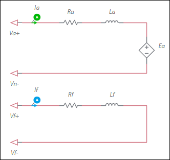
Ea = ωm * If * Laf
where
Ea = back-EMF voltage
ωm = Mechanical angular speed
Laf = Armature-field mutual inductance
If = Field current
The generated electromagnetic torque is:
Te = Ia * If * Laf
| Parameter | Description |
|---|---|
| Armature inductance | Inductance of the armature winding. |
| Armature resistance | Ra in the equation in Deriving Laf from datasheets, below. |
| Field winding inductance | Field inductance. |
| Field winding resistance. | Field resistance. |
| Armature-field mutual inductance | See Deriving Laf from datasheets, below. |
| Shaft inertia | Inertia of the shaft in kg•m<sup>2</sup>. J<sub>rotor</sub> on the machine model diagram in <a href="/help/components/machine-modeling/">Machine modeling</a>. |
| Shaft friction | This is F<sub>rotor</sub> on the machine model diagram in <a href="/help/components/machine-modeling/">Machine modeling</a>. |
| Initial angular speed | Rotational measurement of the shaft angle in rad/s at the start of the simulation. |
| Initial angle | Initial shaft angle in radians. |
Deriving Laf from datasheets
Rearranging the back-EMF equation, Laf can be expressed as:
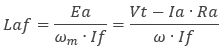
where
Laf = Armature-field mutual inductance
Ea = Back-EMF voltage
Vt = Terminal voltage applied to the machine
ωm = Speed in radians.
Ia = Armature current
Ra = Armature resistance
If = Field current
Datasheets often state voltage, current and speed values at rated conditions. These values can be used directly in the above expression to solve for Laf.
