Synchronous permanent magnet hall
This component is identical to the Synchronous permanent magnet except that it contains an extended set of measurement pins.
Additional connections:
| Connection | Description |
|---|---|
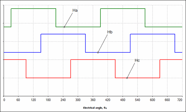
| Ha | Hall sensor A signal. This signal changes in response to changes in the magnetic field. |
| Hb | Hall sensor B signal. This signal changes in response to changes in the magnetic field. |
| Hc | Hall sensor C signal. This signal changes in response to changes in the magnetic field. |
Hall sensor output
The following graph shows the hall sensor output vs. the electrical angle:
θe = θm * P
where
θe = electrical angle
θm = mechanical angle
P = number of rotor pole pairs
This component should only be used in transient-type simulations where Initial conditions are set to User defined.
Simulation and parameter information is the same as the Synchronous permanent magnet model.