Analog Transistor circuit compared to diode circuit
0
Favorite
2
Copy
217
Views

Circuit Description

Circuit Graph
Analog Transistor circuit compared to diode circuit
Transistor switch circuit that consists of NPN BJT (Bipolar Junction Transistor), DC power supply, fuse, switch and resistors.
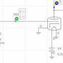
On the right side is another circuit. This one is the Diode circuit that consist of diode, DC power supply, switch and resistor.
I arranged the two circuits side-side to highlight the behavior of the transistor Q1 base-emitter voltage and current. Also, the behavior of diode D1 P-N junction voltage and current. Investigate the similarity of those two during the simulation exercise.
Transistor circuit parameters:
VDC = 5VDC
R1= 330ohm
Rload=330ohm
F1= Fuse, 100mA
Q1=common NPN transistor
S1=ON/OFF switch
Diode circuit parameter:
VDC1=5VDC
Rload1=330ohm
D1=common diode
S2=ON/OFF switch
Answer the following on a separate Word document and email the answers to the instructor.
Deadline of submission will be announced.
Exercise 1:
Run the simulation
What are the voltage and current value when S1 is OFF
Vbase=?
Ibase=?
Vload=?
I_load=?
Exercise 2:
Select S1 until its contact turns ON (wire shorted)
What are the voltage and current value when S1 is ON
Vbase=?
Ibase=?
Vload=?
I_load=?
Did the I_load increased or decreased when S1 in ON?
Exercise 3:
Now go to the Diode circuit at the right side.
What is the voltage and current when S2 is OFF
Vload1=?
I_load1=?
Exercise 4:
Select S2 until its contact turns ON (wire shorted)
What are the voltage and current value when S2 is ON
Vload1=?
I_load1=?
Did the I_load increased or decreased when S2 in ON?
Stop the simulation.
Notice the similarities between the Q1 base-emitter voltage and current compared to D1 voltage and current.
Both of them are almost the same when they are switched ON (when forward bias voltage are applied to its P-N junction).
Notice that Q1 base-emitter junction is also P-N junction.
In addition, I_load current increased due to collector-emitter shorting to ground.
This is how you turn-ON a transistor. Common base-emitter voltage is ~0.7Volt and base current is ~12mA.
Reverse Bias Condition:
Reverse D1 where its P-junction is grounded and N-junction is connected to Rload.
Exercise 5:
Run the simulation
What is the voltage and current when S1 is OFF
Vload1=?
I_load1=?
Exercise 6:
Select S2 until its contact turns ON (wire shorted)
What are the voltage and current value when S2 is ON
Vload1=?
I_load1=?
Did the I_load increased or decreased when S2 in ON?
Did the Vload increased or decreased when S2 in ON?
What you noticed when the diode is reversed bias?
Creator

ChrisCoronel
76 Circuits
Date Created
3 years, 4 months ago
Last Modified
3 years, 1 month ago
Tags


Open Circuit
✕Circuit Graph
✕
There are currently no comments