Green LED Multisim
0
Favorite
0
Copy
311
Views


Circuit Description

Circuit Graph
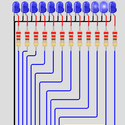
Multisim spelled out using green LEDs.
The purpose of this example is to show how you can use the schematic CONNECTOR. This is the symbol that looks like an arrow and is labeled i01 in the circuit.
The connector lets you connect multiple points on the circuit together without drawing a wire to each point which can get messy at times.
It looks like I'm not using a battery to light up these LEDs but, I have my connector connected to a battery in the bottom right side of the schematic. I am using the connector to connect the positive+ end of the battery to all of the positive+ (anode) points on the LEDs.
Creator

TEHRANGELES⚡
132 Circuits
Date Created
2 years, 4 months ago
Last Modified
2 years, 4 months ago
Tags
Circuit Copied From


Open Circuit
✕Circuit Graph
✕
There are currently no comments