Your browser is incompatible with Multisim Live. Use the Chrome™ browser to best experience Multisim Live.
Configurable transformer
This section applies to all configurable transformer components with the NPMS naming convention. N represents the number of coils on the primary side and M represents the number of coils on the secondary. For reference, the 2P2S configuration is used throughout this section.
The figure below shows the component’s symbol:
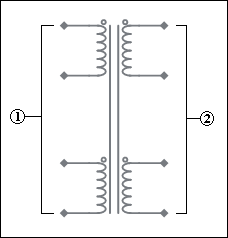
The primary coils (1) are numbered from the top down, as are the secondary coils (2). The dots on the symbol windings are polarity markers. When current enters the dotted terminal of a coil, the polarity of the mutual voltage in the second coil is positive at its dotted terminal.
You can change the number of turns in the primary and secondary windings by selecting the component and viewing its properties. You can also reverse the polarity of any of the windings from the component's properties. The polarity of each coil is represented by the o symbol.
- 555 timer
- 7-segment display
- ABM sources
- AND
- Angle wrap
- Arbitrary sources
- BCD to 7-segment decoders
- Binary Counters
- BJTs
- Brushless DC machine
- Brushless DC machine hall
- Capacitor
- Combination relay
- Configurable transformer
- Creating custom component models
- Current controlled SPST
- D flip-flop
- D latch
- DC machine permanent magnet
- DC machine wound field
- DC voltage/current sources
- Decoders/Demultiplexers
- Delay
- Digital buffer
- Digital clock
- Digital constant
- Diode
- Diode switch
- Divider
- Full Adders
- GaAsFETs
- GTO switch
- Ideal comparator
- Impedance block
- Incremental encoder
- Induction machine squirrel cage
- Induction machine squirrel cage (E)
- Induction machine wound
- Induction machine wound (E)
- Inductor
- Inductor coupling
- Inertial load
- Inverter
- JFETs
- JK flip-flop
- LM555CN - Highly Stable 555 Timer
- Lossy transmission line
- Machine modeling
- MOSFETs
- Multiplier
- NAND
- NOR
- Opamps
- OR
- Phase angle controller
- Phase angle controller 2 pulse
- Phase angle controller 6 pulse
- Potentiometer
- Probes
- Pulse width modulation (PWM) components
- PWM sinusoidal 3 phase
- Relays
- Resistor
- Resolver
- SCR switch
- SPDT switch
- SPST double break
- SPST switch
- SR flip-flop
- SR latch
- Stepper 2 phase
- Stepper 2 phase 2 winding
- Synchronous permanent magnet
- Synchronous permanent magnet E
- Synchronous permanent magnet hall
- T flip-flop
- Three phase delta
- Three phase wye
- Transistor switch
- TRIAC switch
- Voltage controlled SPDT/DPDT
- Voltage controlled SPST
- Voltage differentiator
- Voltage gain block
- Voltage integrator
- Voltage summer
- XNOR
- XOR
- Zener
© 2026 National Instruments Corp. ALL RIGHTS RESERVED.
Hosted Services Terms Privacy Policy Export Notices Terms of Use
