Designing in the mechanical domain
A number of purely mechanical components are available in Multisim Live. You may also use electrical elements directly to model mechanical behavior. For instance, you can connect an independent voltage source to simulate an external force that turns the rotor at a speed equal to the voltage value. External loads may be modeled by attaching models to the rotor pin.
Notice that in the figure in Machine modeling, a capacitor is used to represent rotor inertia. This is because the rotor inertia governs the relationship between the speed and torque in the same way that a capacitor governs the relationship between voltage and current. The same logic applies to the use of a resistor to represent the friction (with the exception that increasing friction tends to increase the amount of torque that is generated whereas increasing resistance tends to decrease the current, so we use 1/Frotor as the resistance value).
The following is an idealized example of a coupled electromechanical system:
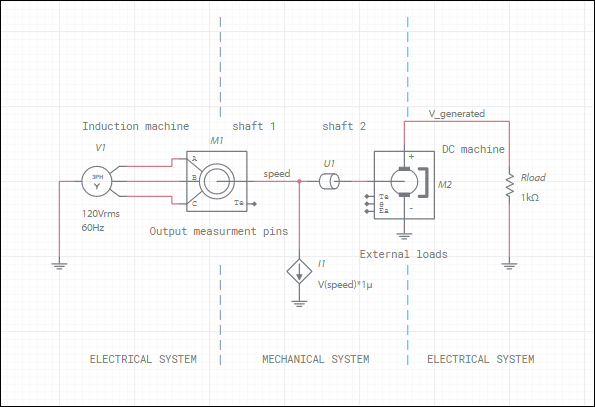
The shaft of induction machine M1 is coupled to the shaft of DC machine M2, which acts as a generator. Additionally, an external speed-dependent load is applied using a controlled current source I1. Because Multisim is programmed to interpret variables as voltages and currents, we must use the V(speed) function in I1 to reference what is actually the rotor speed.
You can probe the voltage on the output measurement pins to measure the stated physical quantity but you should not drive these pins — they act as outputs only.
