Synchronous permanent magnet model
Model assumptions
- Uniform air-gap
- No slot harmonics
- No stator saturation
- Sinusoidally distributed windings
- No zero phase sequence (system is balanced)
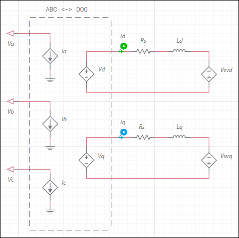
Configuration of the machine electrical system
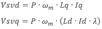
where
P = number of poles
ωm = angular speed
λ = flux linkage induced by the permanent magnet
The elements in the dashed region represent the bidirectional ABC↔DQ0 coordinate transform in the rotor reference frame. Refer to the DQ0 coordinate transforms section for representative equations.
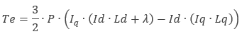
The generated electromagnetic torque, Te, is:
| Parameter | Description |
|---|---|
| d-axis inductance | Combined leakage inductance and magnetizing inductance on d-axis. Ld in the generated electromagnetic torque equation. |
| q-axis inductance | Combined leakage inductance and magnetizing inductance on q-axis. Lq in the generated electromagnetic torque equation. |
| Stator resistance | Rs in the electrical diagram. |
| Magnet flux | Flux linkage induced by the permanent magnet. λ in the equations for Vsvq and Te. |
| Number of pole pairs | P in the equations for Vsvd, Vsvq and Te. |
| Shaft inertia | J<sub>rotor</sub> on the machine model diagram in <a href="/help/components/machine-modeling/">Machine modeling</a>. |
| Shaft friction | This is F<sub>rotor</sub> on the machine model diagram in <a href="/help/components/machine-modeling/">Machine modeling</a>. |
| Initial angular speed | Rotational measurement of the shaft angle in rad/s at the start of the simulation. |
| Initial angle | Initial shaft angle in radians. |
