Your browser is incompatible with Multisim Live. Use the Chrome™ browser to best experience Multisim Live.
Phase angle controller 6 pulse
This component models a basic phase angle controller. It can be used for controlling a thyristor-based three-phase bridge for AC to DC power conversion applications.
It generates pulses on pins T1 through T6 some time delay after a rising zero-crossing event occurs in the phase-to-phase voltages present across pins PhA, PhB, and PhC. The delay is set using the voltage applied to the firing angle pin a. The voltage on this pin is the delay value in degrees.
The time delay, in seconds, is calculated as:
![]()
where
f = Line frequency parameter
α = firing angle (voltage at pin a)
The component also generates six simultaneous pulses of the same width on all output pins when the simulation starts. These pulses provide the initial current flow to the bridge.
For the phase control circuit to function properly, voltages with specific phases must be applied to the PhA, PhB, and PhC pins and thyristors in assumed positions must be connected to pins T1 through T6.
The following shows a correctly set up design.
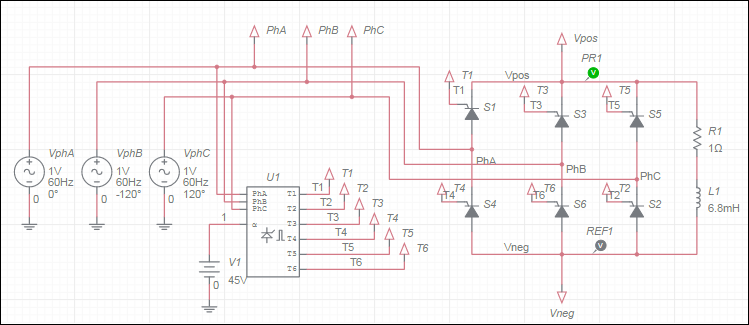
Phase A (VphA) must be connected to the first leg of the bridge, Phase B (VphB) to the second leg, and Phase C (VphC) to the third leg with relative phases 0, -120, and 120 degrees, respectively. Also, note the thyristor connections. The thyristor ordering is based on the natural commutation sequence given the shown AC voltage phases.
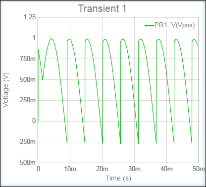
The circuit above is set to fire at an angle of 45° and operates at 60 Hz. It generates the following output.
- 555 timer
- 7-segment display
- ABM sources
- AND
- Angle wrap
- Arbitrary sources
- BCD to 7-segment decoders
- Binary Counters
- BJTs
- Brushless DC machine
- Brushless DC machine hall
- Capacitor
- Combination relay
- Configurable transformer
- Creating custom component models
- Current controlled SPST
- D flip-flop
- D latch
- DC machine permanent magnet
- DC machine wound field
- DC voltage/current sources
- Decoders/Demultiplexers
- Delay
- Digital buffer
- Digital clock
- Digital constant
- Diode
- Diode switch
- Divider
- Full Adders
- GaAsFETs
- GTO switch
- Ideal comparator
- Impedance block
- Incremental encoder
- Induction machine squirrel cage
- Induction machine squirrel cage (E)
- Induction machine wound
- Induction machine wound (E)
- Inductor
- Inductor coupling
- Inertial load
- Inverter
- JFETs
- JK flip-flop
- LM555CN - Highly Stable 555 Timer
- Lossy transmission line
- Machine modeling
- MOSFETs
- Multiplier
- NAND
- NOR
- Opamps
- OR
- Phase angle controller
- Phase angle controller 2 pulse
- Phase angle controller 6 pulse
- Potentiometer
- Probes
- Pulse width modulation (PWM) components
- PWM sinusoidal 3 phase
- Relays
- Resistor
- Resolver
- SCR switch
- SPDT switch
- SPST double break
- SPST switch
- SR flip-flop
- SR latch
- Stepper 2 phase
- Stepper 2 phase 2 winding
- Synchronous permanent magnet
- Synchronous permanent magnet E
- Synchronous permanent magnet hall
- T flip-flop
- Three phase delta
- Three phase wye
- Transistor switch
- TRIAC switch
- Voltage controlled SPDT/DPDT
- Voltage controlled SPST
- Voltage differentiator
- Voltage gain block
- Voltage integrator
- Voltage summer
- XNOR
- XOR
- Zener
© 2026 National Instruments Corp. ALL RIGHTS RESERVED.
Hosted Services Terms Privacy Policy Export Notices Terms of Use
