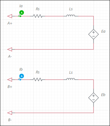
Stepper 2 phase model
Model assumptions
- Linear iron magnetization with no saturation
- Constant self and mutual inductance
- No interaction between phases
- Uniform air-gap
- No slot harmonics
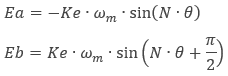
where
Ke = speed constant
ωm = mechanical angular speed
θ = mechanical angle
N = 90°/Step
Step = motor full step angle size in degrees
The generated electromagnetic torque, Te, is:

where
Kt = torque constant
Td = detent torque
The torque constant is:
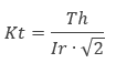
where
Kt = torque constant
Th = holding torque
Ir =rated current
and ![]() accounts for the fact that Th is a result of a vector sum of the two phase torques which are 90° apart.
accounts for the fact that Th is a result of a vector sum of the two phase torques which are 90° apart.
| Parameter | Description |
|---|---|
| Armature inductance | Armature winding inductance in henries. Ls as shown in the configuration of the the machine's electrical system. |
| Armature resistance | Armature winding resistance in ohms. Rs as shown in the configuration of the machine's electrical system. |
| Step angle | Step angle in degrees. As shown in the Ea and Eb equations for this component. This is not in the equation for Te. It is used to calculate N, which is in the equation. |
| Torque constant | Torque constant in Nm/A. |
| Speed constant | Speed constant in V•s/rad. Set this value to that of Kt, unless it is explicitly specified in the datasheet. This is Ke in the Ea and Eb equations. |
| Detent torque | Detent torque in Nm. As shown in the equation for Te. |
| Shaft inertia | Inertia of the shaft in kg•m<sup>2</sup>. J<sub>rotor</sub> on the machine model diagram in <a href="/help/components/machine-modeling/">Machine modeling</a>. |
| Shaft friction | This is F<sub>rotor</sub> on the machine model diagram in <a href="/help/components/machine-modeling/">Machine modeling</a>. |
| Initial angular speed | Rotational measurement of the shaft angle in rad/s at the start of the simulation. |
| Initial angle | Initial shaft angle in radians. |
