Incremental encoder
This component models an ideal optical encoder. It senses the speed input signal, integrates it to deduce the position, and generates a stream of pulse signals in order to provide information about speed and position to a digital controller.
This component is designed to be connected to the shaft of machine components. This component presents neither an inertial nor a frictional load on the shaft.
| Connection | Description |
|---|---|
| w_in, w_out (the shaft) | The connection to the signal that carries angular speed in rad/s as a voltage. Symbolizing a mechanical shaft, these two pins are internally short circuited; it does not matter which of the pins is connected to the speed signal. The secondary pin is available so that other mechanical components, external loads, sensors, or motion controllers can be chained and applied to the shaft, while maintaining the look of a rotary mechanical system. |
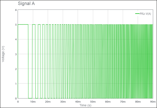
| A | Output pulse train of the lagging signal (lags B by a quarter cycle). |
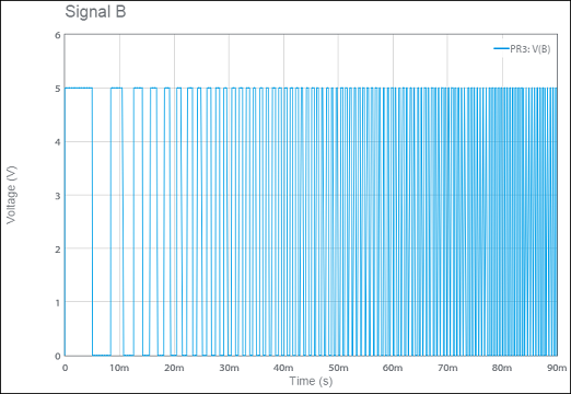
| B | Output pulse train of the leading signal (leads A by a quarter cycle). |
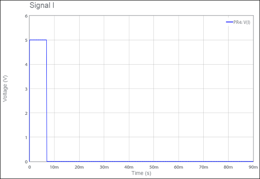
| I | The index signal. A pulse is generated on this pin when the angular position is an integer multiple of 2π. |
Example
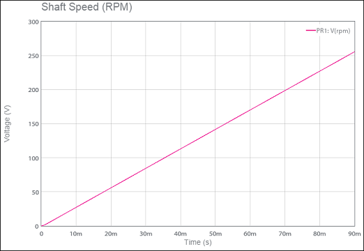
The following example illustrates the start-up of a DC machine and the corresponding encoder signals.
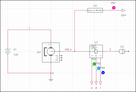
A 90ms transient simulation gives the following results:
This component should only be used in transient-type simulations where Initial conditions are set to User defined.
