Streaming data to Measurements Live
After simulating a design in Multisim Live, you can stream your simulated data to Measurements Live, a web-based application that contains Soft Front Panels (SFPs) for you to access and control the instruments on the NI ELVIS III. You can then prototype the actual circuit with NI ELVIS III, and compare the simulation with real-world measurements inside the Measurements Live environment using the NI ELVIS III Oscilloscope.
Complete the following steps to stream your simulated data from Multisim Live to Measurements Live and compare simulated signals with real signals.
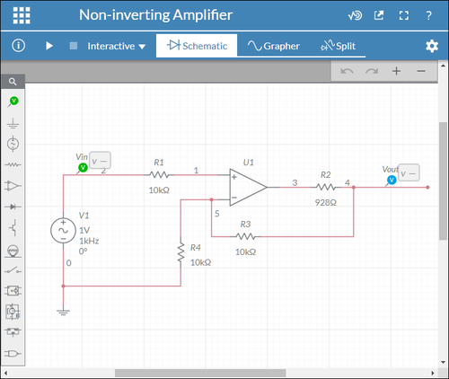
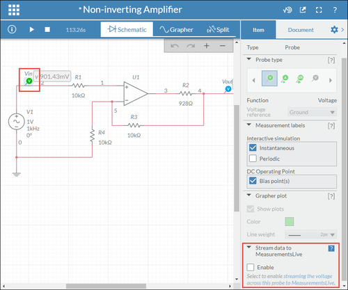
Step 1 - Open your simulation design
Step 2 - Stream simulated data to Measurements Live
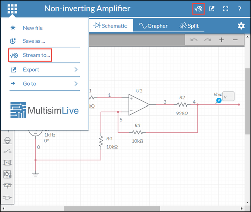
- Click
 either through the access command or the button on the top right.
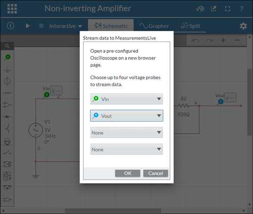
 - Select voltage probe(s) and click OK.
The probe dropdown lists correspond to the four Oscilloscope reference channels respectively.
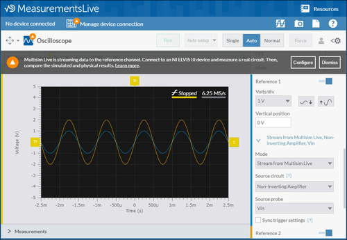
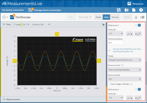
- Observe the streamed simulation on the pre-configured Oscilloscope SFP.
The reference channel of the Oscilloscope SFP is pre-configured based on the circuit and probe you choose to stream in Multisim Live. You can also adjust the settings by going to Additional channels > reference channel on the configuration pane.
- In Multisim Live, click the voltage probe(s) you want to stream and select the Enable checkbox on the configuration pane.
- In Measurements Live, configure the reference channel of the Oscilloscope.
Continue with the following steps if you want to quickly stream more data from other circuits in Multisim Live.
When you select the Enable checkbox for certain probes in the previous step, these probes and their corresponding circuits will appear in the Source circuit and Source probe dropdown lists.
Step 3 - Compare the simulation with real measurements
After streaming your simulated signals to Measurements Live, you can use the NI ELVIS III to prototype a real circuit based on your simulation design. Then, you can compare your simulated signals with real signals on the Oscilloscope SFP to verify your simulation design. Perform the following steps to compare your simulation design with real measurements:
- Build a real circuit on an NI ELVIS III device based on your simulation design.
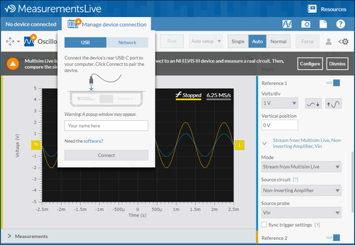
- Connect the NI ELVIS III device to your host computer.
- Click Manage device connection.
- Follow the onscreen instructions to connect to the device. Refer to the NI ELVIS III Manual for more details.
- Wire the circuit that you built to the Oscilloscope channel 1 on the NI ELVIS III.
- Compare the simulation with real measurements on the Oscilloscope SFP.
- The yellow waveform on channel 1 stands for the measured signal.
- The blue waveform on reference channel 1 stands for the simulated signal.
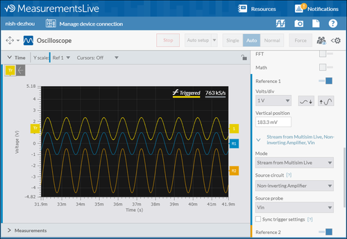
Note that you need to select the Sync trigger settings checkbox if you want to synchronize the simulated signals with real signals to better compare the two.
About the NI ELVIS III
Refer to the NI ELVIS III Manual to learn more about the NI ELVIS III and Measurements Live.
