Your browser is incompatible with Multisim Live. Use the Chrome™ browser to best experience Multisim Live.
JFET model
JFETs are modeled using an equivalent circuit. Model parameters should not be mistaken for datasheet parameters.
See below for details.
Large signal model
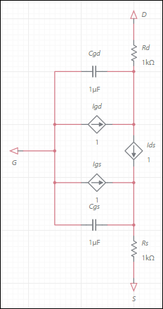
All transistor node voltage references are with respect to the internal nodes in the following equations (that is, the ohmic resistance pin that is connected the inside of the structure.)
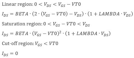
Static equations
Drain-source current:
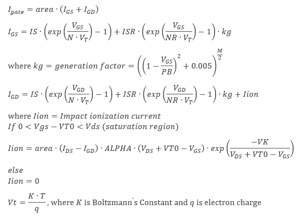
Gate currents:
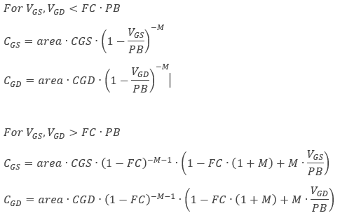
Capacitances
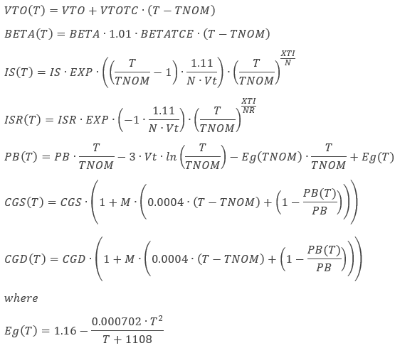
Temperature dependent parameters:
The following parameters are functions of temperature. T is the operating temperate and TNOM is the nominal (or measured) temperature. T and TNOM can be adjusted in a number of ways.
Noise equations
The device has thermal noise generators, ![]() and
and ![]() , as a result of the series ohmic resistances,
and the shot and flicker noise generators, collectively
, as a result of the series ohmic resistances,
and the shot and flicker noise generators, collectively ![]() , as a result of the PN junction.
, as a result of the PN junction.
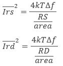
Ohmic resistance noise:
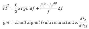
Shot and flicker noise:
References
- G. Massobrio and P. Antognetti, Semiconductor Device Modeling with SPICE, 2nd edition, McGraw-Hill, 1993.
- A. Vladimirescu, The SPICE Book, Wiley, 1994.
- 555 timer
- 7-segment display
- ABM sources
- AND
- Angle wrap
- Arbitrary sources
- BCD to 7-segment decoders
- Binary Counters
- BJTs
- Brushless DC machine
- Brushless DC machine hall
- Capacitor
- Combination relay
- Configurable transformer
- Creating custom component models
- Current controlled SPST
- D flip-flop
- D latch
- DC machine permanent magnet
- DC machine wound field
- DC voltage/current sources
- Decoders/Demultiplexers
- Delay
- Digital buffer
- Digital clock
- Digital constant
- Diode
- Diode switch
- Divider
- Full Adders
- GaAsFETs
- GTO switch
- Ideal comparator
- Impedance block
- Incremental encoder
- Induction machine squirrel cage
- Induction machine squirrel cage (E)
- Induction machine wound
- Induction machine wound (E)
- Inductor
- Inductor coupling
- Inertial load
- Inverter
- JFETs
- JK flip-flop
- LM555CN - Highly Stable 555 Timer
- Lossy transmission line
- Machine modeling
- MOSFETs
- Multiplier
- NAND
- NOR
- Opamps
- OR
- Phase angle controller
- Phase angle controller 2 pulse
- Phase angle controller 6 pulse
- Potentiometer
- Probes
- Pulse width modulation (PWM) components
- PWM sinusoidal 3 phase
- Relays
- Resistor
- Resolver
- SCR switch
- SPDT switch
- SPST double break
- SPST switch
- SR flip-flop
- SR latch
- Stepper 2 phase
- Stepper 2 phase 2 winding
- Synchronous permanent magnet
- Synchronous permanent magnet E
- Synchronous permanent magnet hall
- T flip-flop
- Three phase delta
- Three phase wye
- Transistor switch
- TRIAC switch
- Voltage controlled SPDT/DPDT
- Voltage controlled SPST
- Voltage differentiator
- Voltage gain block
- Voltage integrator
- Voltage summer
- XNOR
- XOR
- Zener
© 2026 National Instruments Corp. ALL RIGHTS RESERVED.
Hosted Services Terms Privacy Policy Export Notices Terms of Use
