Stepper 2 phase 2 winding model
Model assumptions
- Linear iron magnetization with no saturation
- Constant self and mutual inductance
- No interaction between phases
- Uniform air-gap
- No slot harmonics
- Perfect coupling between intra-phase windings
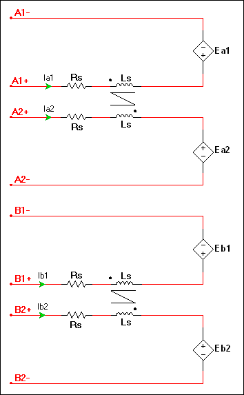
Configuration of the machine electrical system
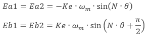
where
Ke = speed constant
ωm = mechanical angular speed
θ = mechanical angle
N = 90°/Step
Step = motor full size angle in degrees
The generated electromagnetic torque is:
![]()
where
Kt = torque constant
Td = detent torque
| Parameter | Description |
|---|---|
| Armature inductance | Armature winding inductance in henries. Ls as shown in the configuration of the machine’s electrical system. |
| Armature resistance | Armature winding resistance in ohms. Rs as shown in the configuration of the machine’s electrical system. |
| Step angle | Step angle in degrees. Used to calculate N. |
| Torque constant | Torque constant in N•m/A. If neither this value nor Ke are specified on the datasheet, Kt can be estimated from any sample on the static holding torque (Th) and rated current curve. |
| Speed constant | Speed constant in V•s/rad. This is typically equal to Kt. This is Ke in the Ea1 and Eb1 equations. |
| Detent torque | Detent torque in N•m. |
| Shaft inertia | J<sub>rotor</sub> on the machine model diagram in <a href="/help/components/machine-modeling/">Machine modeling</a>. |
| Shaft friction | This is F<sub>rotor</sub> on the machine model diagram in <a href="/help/components/machine-modeling/">Machine modeling</a>. |
| Initial angular speed | Rotational measurement of the shaft angle in rad/s at the start of the simulation. |
| Initial shaft angle | Initial shaft angle in radians. |
