Your browser is incompatible with Multisim Live. Use the Chrome™ browser to best experience Multisim Live.
Pulse width modulation (PWM) components
Multisim includes the PWM, PWM Complementary, and PWM 3 Phase generators.
These components model simple PWM generators. The PWM component's model consists of a comparator and a triangular waveform generator as shown below.
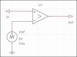
The model parameters Frequency, TriangleMin, and TriangleMax are used to set up the reference triangular voltage source Vref.
The model parameters OutputVoltage, RiseFallTime, and PwmMode are used to set up the ideal comparator U2.
The rise/fall times force the output to change as a ramp with a duration equal to the value of the rise/fall time parameter. When selected, PwmMode detects crossings in the input signals and cuts back the simulation time step during such an event. This ensures a highly accurate PWM signal. Delays to simulation time for this algorithm are negligible in the vast majority of cases, so we recommend that you leave this parameter selected.
Example:
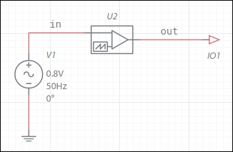
Parameters used:
Frequency: 1 kHz
TriangleMin: -1 V
TriangleMax: 1 V
OutputVoltage: 5 V
RiseFallTime: 1 ns
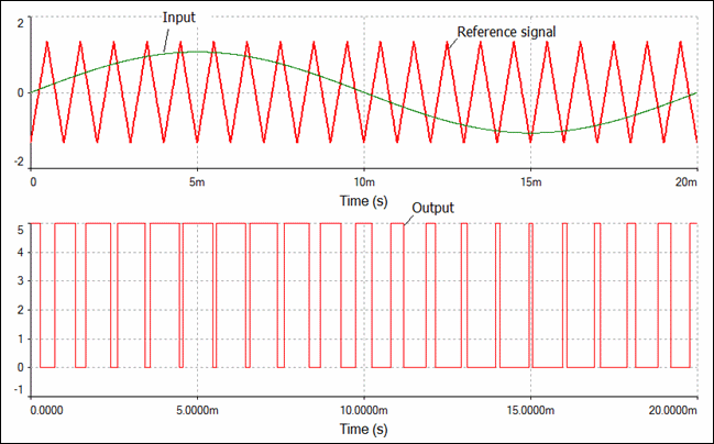
Result:
The PWM Complementary component contains an additional output pin for the complement of the output.
The PWM 3 Phase component consists of three identical PWM Complementary components. They share the same reference signal.
- 555 timer
- 7-segment display
- ABM sources
- AND
- Angle wrap
- Arbitrary sources
- BCD to 7-segment decoders
- Binary Counters
- BJTs
- Brushless DC machine
- Brushless DC machine hall
- Capacitor
- Combination relay
- Configurable transformer
- Creating custom component models
- Current controlled SPST
- D flip-flop
- D latch
- DC machine permanent magnet
- DC machine wound field
- DC voltage/current sources
- Decoders/Demultiplexers
- Delay
- Digital buffer
- Digital clock
- Digital constant
- Diode
- Diode switch
- Divider
- Full Adders
- GaAsFETs
- GTO switch
- Ideal comparator
- Impedance block
- Incremental encoder
- Induction machine squirrel cage
- Induction machine squirrel cage (E)
- Induction machine wound
- Induction machine wound (E)
- Inductor
- Inductor coupling
- Inertial load
- Inverter
- JFETs
- JK flip-flop
- LM555CN - Highly Stable 555 Timer
- Lossy transmission line
- Machine modeling
- MOSFETs
- Multiplier
- NAND
- NOR
- Opamps
- OR
- Phase angle controller
- Phase angle controller 2 pulse
- Phase angle controller 6 pulse
- Potentiometer
- Probes
- Pulse width modulation (PWM) components
- PWM sinusoidal 3 phase
- Relays
- Resistor
- Resolver
- SCR switch
- SPDT switch
- SPST double break
- SPST switch
- SR flip-flop
- SR latch
- Stepper 2 phase
- Stepper 2 phase 2 winding
- Synchronous permanent magnet
- Synchronous permanent magnet E
- Synchronous permanent magnet hall
- T flip-flop
- Three phase delta
- Three phase wye
- Transistor switch
- TRIAC switch
- Voltage controlled SPDT/DPDT
- Voltage controlled SPST
- Voltage differentiator
- Voltage gain block
- Voltage integrator
- Voltage summer
- XNOR
- XOR
- Zener
© 2026 National Instruments Corp. ALL RIGHTS RESERVED.
Hosted Services Terms Privacy Policy Export Notices Terms of Use
