Convergence
Most circuits contain non-linear elements such as diodes and transistors. To solve the non-linear set of equations formed by these elements, the simulator uses an iterative method called Newton-Raphson. The method involves successively linearizing and solving the circuit until the differences in the solutions between successive iterations become sufficiently small, a condition referred to as convergence. The Newton-Raphson method is used by all analyses.
To learn more about how the Newton-Raphson method works, refer to the Linearization section of Analog simulation.
Resolving non-convergence
Many factors affect the ability of the simulator to converge, including model complexity and model parameters, circuit topology, and the simulator settings. It is suggested to inspect the model parameters and circuit to determine whether any modifications are warranted, prior to adjusting the simulator settings.
- Use realistic parameter values - Do not use resistances with values less than 1µΩ. Also avoid using unrealistically small inductors and unrealistically large capacitors. These lead to very large conductance values in the simulation matrix and may cause numerical difficulties which negatively impact convergence.
- Use simpler models when possible - Using simplified models not only aids convergence but also improves simulation speed. For instance, if you are studying the general topological behavior of a switching power circuit, consider using components with idealized models (found in the Power group in the palette) to model the switching function of the MOSFET, IGBT, or diode elements.
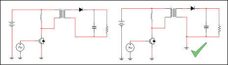
- Avoid isolation - Try to
avoid floating nodes. For example if you are simulating a circuit with a
transformer, consider grounding the secondary side of the transformer as shown
below, on the right. If the modeling of isolation is required, connect the
secondary side to ground using a 1MΩ resistor.
- Remove unused or unnecessary components - You might have components or circuits that are not related to the primary circuit being studied. These components or circuits put more stress on the simulator, and might negatively affect its ability to converge. Consider removing these components.
You can loosen the current, voltage, and relative tolerances that the simulator uses to determine whether a solution has converged, using the ABSTOL, VNTOL, and RELTOL settings respectively. You can also increase the maximum number of iterations that the simulator uses to try to achieve convergence, using the ITL4 and ITL1 settings.
These are located in the right properties pane under Simulator Options.
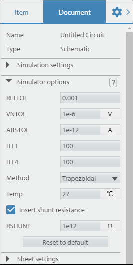
Apply the suggested values sequentially in the order shown, re-simulating as you apply each individual one.
| Option name | Adjusted value | Comment |
|---|---|---|
| ABSTOL | 1e-8 | This loosens the absolute current tolerance. The default tolerance of 1e-12A is not required for many designs, particularly power circuits. Do not increase beyond 1e-6A. |
| VNTOL | 1e-4 | This loosens the absolute voltage tolerance. The default tolerance of 1e-6V is not required for many designs, particularly power circuits. Do not increase beyond 1e-3V. |
| RELTOL | 0.01 | This loosens the relative voltage and current tolerances. Do not increase beyond 0.01. |
| ITL4 | 100-500 | This is the maximum number of iterations the Newton-Raphon method takes during the calculation of each time-domain time point before non-convergence for the time-point is declared. If the simulator cannot converge with 500 iterations, increasing the number of iterations further is unlikely to help. |
| ITL1 | 100-500 | This is the maximum number of iterations the Newton-Raphon method takes during the calculation the DC operating point before non-convergence is declared. If the simulator cannot converge with 500 iterations, increasing the number of iterations further is unlikely to help. |
