.subckt definitions
A SPICE subcircuit (.subckt) wraps around a block of circuit text and allows external connections to this circuitry only through the subcircuit's nodes.
Because the internal circuitry is isolated from external circuitry, internal devices and node names with the same names as those external to the subcircuit are neither conflicting nor shorted. In addition, subcircuits can accept circuit parameters which can be used to assign values to internal devices or nested subcircuits.
For more information on .subckt definitions, including examples, refer to SPICE subcircuits.
Using a .subckt definition:
- Place one of the above components on the workspace.
- Select the component and tap the configuration button
 in the toolbar to open the configuration pane.
 - Select User-defined .subckt from the Model drop-down.
For example, for a diode: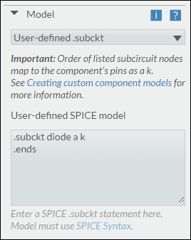
- Enter a valid .subckt definition in the text box, for example,
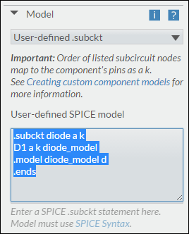
Caution. We recommend that the model be placed into the netlist hierarchically, meaning that all child subcircuits are within the parent. For example:
.subckt parent 1 2 3
x1 1 2 3 child
.subckt child 1 2 3
.ends
.ends
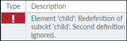
If the subcircuits are not entered hierarchically, there is the potential for conflicts in the netlist, which would result in netlist errors. For example if the netlist above is entered as follows,
.subckt parent 1 2 3
x1 1 2 3 child
.ends
.subckt child 1 2 3
.ends
and there are two copies of the component containing that custom model in your design, you will get the following netlist error:
.subckt pin order
You may wish to copy existing .subckt definitions and paste them into the User-defined SPICE model field. However, these definitions may not have the component’s pins mapped in the correct order.
Each device capable of using a user-defined .subckt includes a note with the correct pin order.
Consider the following example for a 5-terminal opamp. Notice that the component pins must be in the order in+, in-, vs+, vs-, and out.
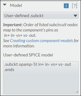
Now consider this snippet from the beginning of a .subckt definition:
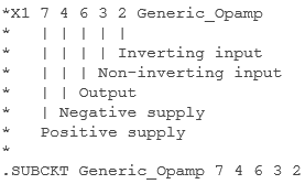
The specified pin order is vs+, vs-, out, in+, and in-.
Because this does not match the required pin order of in+, in-, vs+, vs-, and out, simulation results will not be as expected.
In this case, the pin order must be changed to:
.SUBCKT Generic_Opamp 3 2 7 4 6
