Machine modeling
A number of electromechanical and mechanical models are available in Multisim. Like the electrical network domain, the mechanical network domain is characterized by two variables: an across-variable and a through-variable.
In the case of electrical domain, these two variables are voltage and current.
In the case of the mechanical domain, these two variables are angular speed and torque. The mechanical models in Multisim use through-variables to represent torque and across-variables to represent angular speed. Therefore when working with mechanical variables in Multisim, voltage represents angular speed (in rad/s) and current represents torque (in N•m).
The mechanical components in Multisim are modeled by machines.
The following depicts the important elements inside an arbitrary machine model. Each model contains an electrical and a mechanical sub-system.
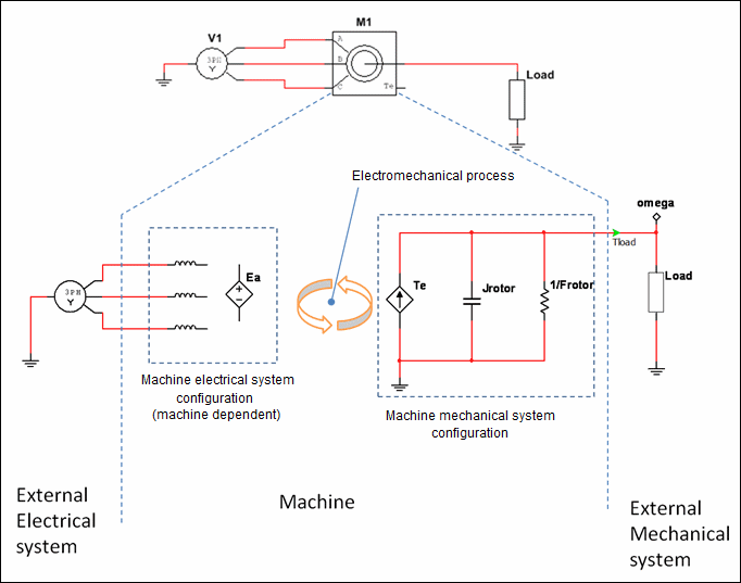
The output pin connecting the machine to the external mechanical system represents the machine rotor or shaft. The voltage on this pin represents the angular speed of the rotor. The torque consumed or produced by any element is measured as the current through that element.
The machine's electrical system configuration is dependent on the machine type and the level of detail in the model. The details of the electrical system are documented under the specific machine types.
Remember that through the electromechanical process (which is dictated by Faraday's laws of induction), the electrical system state is dependent on the mechanical system state. For example, for a simple DC motor model, the faster the shaft spins the larger the back-EMF voltage that counteracts the induced current in the windings. Another example is an induction motor, where the effective inductances are a function of the rotor position.
The machine’s mechanical system state is dependent on the machine’s electrical system state. However, unlike the electrical system configuration, the mechanical system configuration is not dependent on the machine type. It is always represented as shown in the figure above—by a torque generator Te, rotor inertia Jrotor, and rotor friction Frotor. Therefore, the torque Tload that is available to the load is:
![]()
The actual value of Te is dependent on the state and type of machine that is generating this torque.
All machines have measurement pins that indicate various dynamic variables such as generated electromagnetic torque, shaft angle, and flux linkage. The value of these measurements is read as a voltage directly at the pin.
