Induction machine squirrel cage model
Model assumptions
- Linear iron magnetization with no saturation
- Uniform air-gap
- No slot harmonics
- Sinusoidally distributed windings
- No zero phase sequence (system is balanced)
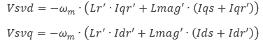
where
ωm = mechanical angular speed
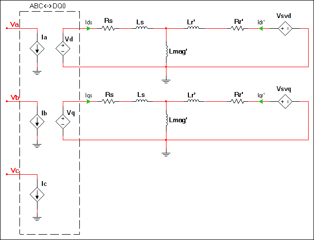
The elements in the dashed region represent a bidirectional ABC<->DQ0 coordinate transform in the stationary reference frame. Refer to DQ0 coordinate transforms for representative equations.
The generated electromagnetic torque is as follows:
![]()
where
P = Number of pair poles
| Parameter | Description |
|---|---|
| Stator leakage | Ls in the diagram of the component’s electrical system. |
| Stator resistance | Rs in the diagram of the component’s electrical system. |
| Rotor leakage inductance | Lr' in the Vsvd and Vsvq equations. |
| Rotor resistance | Rr' in the diagram of the component’s electrical system. |
| Magnetizing inductance | Lmag' in the Vsvd and Vsvq equations. |
| Number of pole pairs | P in the equation for generated electromagnetic torque. |
| Shaft inertia | J<sub>rotor</sub> on the machine model diagram in <a href="/help/components/machine-modeling/">Machine modeling</a>. |
| Shaft friction | This is F<sub>rotor</sub> on the machine model diagram in <a href="/help/components/machine-modeling/">Machine modeling</a>. |
| Initial angular speed | Rotational measurement of the shaft angle in rad/s at the start of the simulation. |
